Connection diagram of a heat accumulator to a solid fuel boiler
 The cost of resources used to heat the coolant in winter is constantly becoming more expensive. This forces the consumer to use equipment that can reduce energy costs to create comfortable conditions when operating autonomous heating systems.
The content of the article
Functions and design of the heat accumulator
 Owners of private houses who switched to using solid fuel boilers burning wood were faced with the need to spend a lot of time and effort on ignition, laying firewood, and monitoring the combustion process. To avoid these difficulties, the heating system is equipped with a thermal energy storage device.
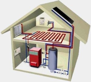
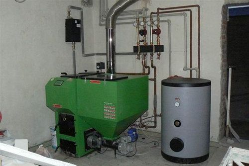
Outwardly, it resembles a boiler, but larger in size, primarily due to a thicker layer of insulation to retain heat. It is not possible to place it in a residential building. Such a unit does not always find a place in the boiler room. To install it, you have to rebuild the furnace rooms or make an extension to them.
Structurally, the following types of heat accumulators are distinguished:
- with an internal boiler - to maintain the required hot water temperature;
- with a heat exchanger (one or several in the form of a spiral);
- with an empty tank.
A cylindrical container, lined with material with high thermal insulation properties, is designed to store hot coolant or water and transfer it to the consumer at the required time. It is this ability of the heat accumulator that allows you to fire up the boiler instead of several times a day, limit yourself to a single heating, and then use the heat from the installed storage tank.
Use of heat accumulators for solid fuel boilers
 Connecting a storage tank for heat conservation helps to use the thermal energy of a solid fuel boiler with greater efficiency. In addition, the drive increases the operating time of the heating system on one load, which allows you to operate the wood-burning unit in a more convenient mode.
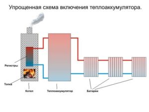
The peculiarity of using a heat accumulator is that when wood burns, the boiler transfers heat first to the storage tank, and then to the heating devices. When the solid fuel is exhausted, the automation transfers the function of a heat source to a storage tank, which gradually, from top to bottom, releases the accumulated thermal energy to the heating system to maintain the set parameters.
Depending on the power of the boiler and the area of the living space, the storage model is selected. There are several simple formulas to determine the battery size:
- The calculation unit is approximately 40 liters per 1 kW of boiler thermal power. For example, for a unit with a power of 10 kW, a tank of 350–450 liters is used.
- Another method for calculating the volume of a storage device recommends multiplying the heated area by 4. Take the resulting value as a basis when choosing equipment. For example, for a house with an area of 70 square meters. m, it would be acceptable to use a container of 280–300 liters.
IMPORTANT! When choosing a heat accumulator, you should not chase large sizes. If the storage capacity is very high, the boiler may not be able to cope with heating the coolant for the heating system and the tank at the same time!
Connecting a solid fuel boiler with a heat accumulator
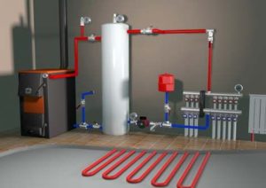
 Connecting a heat storage device to the heating system will look like installing two heat sources. It is only necessary to take into account the possibility of transferring coolant from the boiler to the tank. To do this, the battery tank is placed between the solid fuel unit and the radiators. To achieve greater heat transfer efficiency, after each of these sources a small circulation circuit is created, equipped with three-way valves.
The movement of coolant from the heat source to the radiators occurs due to natural or forced circulation of water in the heating system. When using a thermal accumulator, the maximum effect is achieved using two circulation pumps. One is installed in front of the boiler, and the other is installed after the storage tank, in front of the plumbing heat recovery devices. The use of natural circulation flows will require great precision in the installation of pipes along the calculated slopes and must have the calculated cross-sections of the “supply” and “return” mains.
When the first pump installed in front of the boiler is operating, the coolant is directed into the “supply” line, which runs in the direction of the storage tank and radiators. Turning on the second pump with the appropriate position of the three-way valve will direct heat to the heating devices installed in the room.
The operation of pumps and three-way valves can be controlled manually or automatically, based on data from temperature sensors that will issue commands depending on the temperature of the coolant.It is recommended to install sensors on the “return” of the boiler, storage tank and heating main. Reducing the temperature of small circuits or the entire system gives a command to open the corresponding valve, and as the degrees increase, it closes the taps.
With manual control, the pipelines are equipped with thermometers to control the “supply” and “return” temperatures. The operating principle of the pumps boils down to the fact that when small circuits are simultaneously turned on and closed using taps, the coolant will flow directly to the heating devices. This mode is appropriate when cooling the room and igniting a solid fuel boiler. As the room and the coolant in the system warm up, the second pump will turn off, and the heated water will flow into the heat accumulator.
The operation of the first pump and the small boiler circuit will allow the heat source to first heat up itself, and then direct the coolant into the main line. Manual control of the directions of heated water flows is carried out only after studying the principle of operation of a storage tank with a solid fuel unit.
ATTENTION! The automation connection is installed based on carefully carried out calculations! The possibility of overheating of the coolant above 95 degrees must not be allowed!
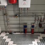
When performing installation work on piping the boiler and heat accumulator, it is necessary to install a safety group and an expansion tank in places specified by the requirements for heating systems.
Connection diagram
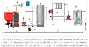
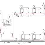
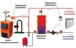 The installation of a solid fuel boiler with a heat accumulator is carried out in accordance with the scheme, which provides for the transfer of coolant from the heat source to the radiators, through the storage tank. A graphical representation of the location of all components and devices takes into account the specific connection sequence, depending on the characteristics of each element of the heating system. The installation diagrams are varied, they show the presence of small circulation circuits, sensors, three-way valves and pumps that provide the required mode to create comfortable conditions in the room.
REFERENCE! Manufacturers of thermal tanks recommend various connection diagrams, which are included in the technical documentation. The practice of installing such equipment shows that it is more important to use the design documentation of the heating system for installing storage tanks, which takes into account the required mode of coolant supply when heating the room! This allows the heat reservoir to be used more efficiently!
Proper selection and correct connection of the storage tank to maintain the set temperature in the house will allow you to light the solid fuel boiler much less often. The ability of the storage device to store the received thermal energy for a long time will make the use of firewood or coal more efficient and save money by reducing the resources consumed.


With such a system, I think much more fuel will be consumed. After all, you also need to heat water in the heat accumulator, and there is a lot of it there.