Headphone jack pinout
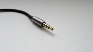 Headphones are an extremely useful accessory with which you can not only listen to music without distracting others, but also watch movies, play any media files, and also communicate with loved ones using programs designed for this. But sometimes it becomes necessary to make some kind of headphone repair. To do this, you need to know their pinout - information about the location of the contacts or, more simply, the internal structure of the accessory. You will learn about how different connectors differ from each other, about circuit diagrams and headphone repair in general in this article.
The content of the article
Types of headphone connectors
The round connectors into which this device is inserted are familiar to every modern person. But not everyone pays attention to the fact that they differ in size.
Headphones can be connected to a huge number of different household appliances: to a TV, computer, smartphone or music player. By size, connectors are divided into three groups. Each of them has the word Jack in its name, which means “nest” in English. The word, easy to remember and pronounce, has made its way into the Russian language and is now used by a large number of users.
- Jack or big jack. 6.25 mm connector, which is used in a professional environment.Musicians often have to interact with it - microphones, guitars and other instruments needed for professional needs have suitable plugs.
- Mini-jack - 3.5 mm. The most common connector in common household devices. Used in phones, laptops, TVs and other devices to which you can connect regular headphones or a headset.
- Microjack. The smallest option, its size is only 2.5 mm. Used in some small phones and music players.
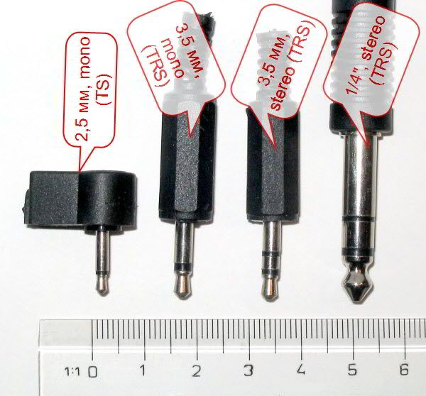
Mini-jack connectors, which are most popular nowadays, are also classified into several types depending on the number of wires: two-pin, three- and four-pin. The first option is now practically not used; it can only be found in the oldest models of devices.
Three-pin headphones are a common accessory, two wires of which are the left and right channels, and the third is the common one. If there is a fourth cable, this is already a headset - headphones with a microphone, which most often come with most smartphones and phones.
In order to make high-quality and correct repairs, you need to know the internal structure of the headphones. Each model has its own, so you should definitely pay attention to this point.
Pinout diagrams for headphone jacks with and without microphone
The pinout diagram for a headset and regular headphones differs in the number of wires, as mentioned above. In addition, there may be other differences depending on the manufacturer and model of the device.
The plug of conventional three-pin headphones is called TRS - an abbreviation for three English words “ring, sleeve and tip”.Using the circuit, you can repair a broken plug, damaged wires, and so on.
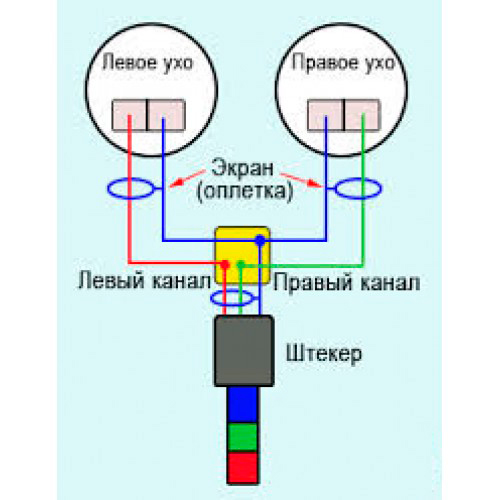
To do this, you will need to unsolder the device and solder it again, taking into account the features of your model.
The four-pin connectors are called TRRS and come in two types: CTIA and OMTP. A feature of each type will be the location of two contacts - a common one and a microphone. They can be either closer to the wires or closer to the tip of the connector.
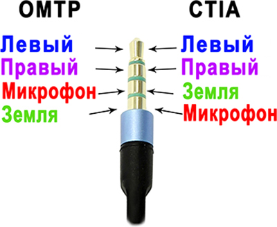
IMPORTANT! When purchasing a headset, it is important to determine the type of device. If you connect it to a different type of system, the sound will be muffled and of poor quality, and the microphone will not work at all.
Headphone repair
Depending on the problem you encountered, you can make various headphone repairs yourself. For example, replace the plug.
To do this, you will need to cut off the plug, and then prepare the cable for work as follows: you need to separate the copper wire from the two channels so that you get only four cables. Then the two copper ones are connected, after which you can begin to remove the insulation. This can be done by heating the wire for not too long. Remove any remaining varnish with any sharp object.
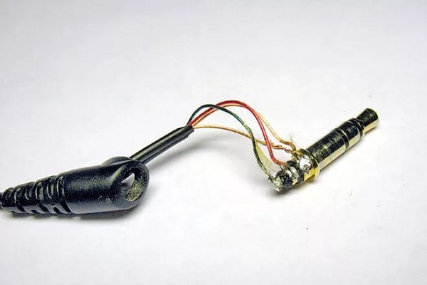
Inside you will see three contacts. The cable must be threaded through the upper half of the connector and the cover inserted into the metal base.
After this, the ends of the wires must be processed using solder and a soldering iron. To complete the next stages of work, you will need a pinout diagram for your particular headphone model. It is important that the connection between the cable and the terminal is fairly reliable. The cable must be inserted into the hole and wrapped several times.
Check the operation of the speakers. Don't be alarmed by rustling or other strange sounds that may occur - they will disappear as soon as you finish the job. If everything is in order, then you can solder the parts to each other in the right places. Then the contacts are crimped with pliers.
Now you know what the pinout of headphone connectors is, why circuits are needed and how to make a not too complicated repair of the device. With this knowledge, you won’t have to spend money on paying for specialist services or buying a new accessory.

