Screw compressor: we understand what it consists of and how it works
In this article you will learn what a screw compressor is, what the design of a screw compressor is, how a screw compressor works, the advantages of screw compressor models.
The content of the article
Screw compressor - what is it. Features and characteristics of rotary compressors
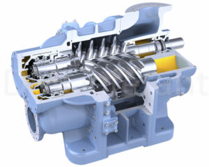
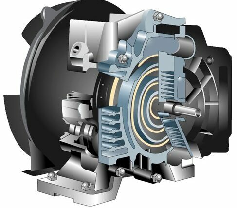
A screw compressor is a type of compressor, a device for compressing air and storing it for later use. In screw models, gas/air is compressed by two rotors. Rotors are also called propellers, hence the name.
The first patented screw compressor was designed in the 30s of the 20th century. Screw compressors are second only to piston compressors in popularity. This is due to their efficiency, small dimensions, light weight, reliability, autonomy, energy efficiency, ease of installation, and low vibration levels. Because of the latter, screw models do not need a special foundation to function properly, which is why they are used by first responders in shipbuilding/placement on ships.
The characteristics of rotary devices are superior to their analogues - maximum air pressure is 15 atmospheres, productivity reaches 100 cubic meters per minute.
Advantages of screw compressors
Advantages of rotary compressors over piston ones:
- Less oil consumption.Oil consumption in rotary compressors is from two to three milligrams per cubic meter of pumped air.
- Cleaner air, no filters needed to power pneumatic equipment. This comes from lower oil consumption.
- They vibrate and make less noise than piston compressors. No special foundation is needed to dampen vibrations.
- Lighter than piston models.
- There is air cooling. That is, no water supply is required to cool the compressed air, and the heat generated during operation of the compressor can be reused for heating the room.
- More reliable and secure.
- Easy to control and operate.
- Can work for long periods of time without breaks.
- They do not require technical inspection for a long time.
- There are automatic operation and self-shutdown systems.
Screw compressor design
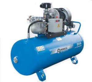
Elements of a classic rotary compressor:
- Primary air filters. When air enters the unit, it passes through one or more filters to remove dust and large dirt. The filters themselves consist of several layers. One is mounted on top of the housing on the air intake tube, the second is installed on the tube with the valve.
- Check valve. Thanks to it, oil from the working chamber and compressed air do not escape back into the atmosphere - it blocks the exit. It works mechanically - it closes from air pressure, opens from low pressure in the chamber. Equipped with a spring.
- Working unit – main chamber and two screws/rotors. In this chamber, the rotors compress the air. The rotors themselves are two large screws with threads that, when rotated, hermetically seal part of the space. The screws are the most expensive part of the compressor. There are several sensors in the chamber, one of them is for adjusting the temperature of the screws.It is located near the air outlet pipe/pipe. The compressor automatically turns off when the outlet temperature reaches 105 degrees at the screws. Otherwise, the equipment will become unusable due to overheating of the device.
- Drive unit. It can be direct (torque from the motor/engine is directly transmitted to the propellers) and belt (the belt is securely tensioned between the shafts of the propellers and the motor; when the motor shaft rotates, the rotor shaft also rotates). Direct ones are more efficient, but they also take up more space and are more difficult to repair, so belt-driven models are more common. The belt itself consists of two connected pulleys. Belt models with high rotation speeds increase productivity and reduce pressure.
- Belt/pulleys. The kit comes with several belts/pulleys of different sizes. Thanks to them, you can regulate the rotation speed.
- Motor or motor. A classic electric motor that rotates the screws directly through the shaft or using a belt. To protect it, a thermal sensor is provided - when it warms up to the maximum permissible temperature (depending on the specific engine model), the sensor sends a signal to the control panel, then the engine contacts open until it cools down. This solution extends the service life of the engine and prevents accidents.
- Oil filter. It is needed to clean the oil from large contaminants before it enters the rotors. It is located in front of the oil supply pipe in the working chamber.
- Oil separation chamber. Air enters here after compression. After the compression process, it contains a lot of oil. To avoid contaminating pneumatic equipment, you need to clean it. To do this, the air is swirled, and due to centrifugal force, different weights, and thickness, oil droplets are separated from the air masses.They pour it into a container, from where the oil is fed back.
- Oil filter. This is the second stage of cleaning the air from oil. After most of the oil has been separated from it, the air passes through this filter. At the outlet, the oil content in it does not exceed 1.4 milligrams per cubic meter of air. No other piston compressor cleans the air this way.
- Safety valve. Often called a safety valve. Triggers when the pressure in the oil separation chamber exceeds the permissible level. This valve closes the air supply to the compartment, after which the compressor stops working.
- Thermostat. The device bypasses cool oil to cool it faster.
- Oil cooler. When air is compressed, it heats up. The temperature rises to 107-180 degrees Celsius. The oil comes into contact with air, so it also heats up. The hot oil enters the cooler, where it cools down.
- Air cooling chamber. The air is cooled here. We mentioned above that in the compressor the compressed air is heated to a temperature of 107-180 degrees. It is unsafe to use compressed air that is so hot, so the compressor is equipped with an air cooler. Here the compressed gas is cooled to a temperature 10-20 degrees Celsius higher than the ambient temperature.
- Fan. The main task of a fan in a compressor is to draw in air for compression. The device is placed so that it additionally cools the equipment.
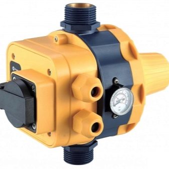
- Pressure switch. Automates the operation of the compressor - measures the pressure in the system, when it reaches a certain level, opens the motor contacts, and the compressor stops. The latest models have electronic panels.
- Pressure gauge. Measures the pressure in the compressor.Installed on the front panel so the user can monitor the pressure.
- Air outlet tube.
How does a screw compressor work?
The operating principle of a rotary compressor is as follows:
An electric motor rotates the propeller shaft through a belt. Above the working chamber with rotors there is a hole or tube with a fan for air intake. The screws themselves are designed in such a way that when you connect their sides, a sealed section is formed. Air enters this section. The screws move air in portions to the air exhaust tube. To make it easier for the rotors to rotate, they are lubricated with oil, which causes the escaping air to be mixed with oil. The mixture enters the cleaning chamber through the outlet tube. There the air is swirled, due to centrifugal force, different masses, densities and thicknesses, the oil flows down and the air masses rise. There they pass through the oil filter, almost completely cleared of oil. When gas is compressed, it heats up. The air in the compressor heats up to 107-180 degrees Celsius, so it needs to be cooled. After the cleaning chamber, it enters the radiator through a tube, where it is cooled. Compressed gas comes out through the pipe. The oil comes into contact with air, so it also heats up. After the cleaning chamber, it also enters the radiator, where it is cooled. The mixture is then transported through the tubes back to the rotors for reuse. On the way, it passes through the oil filter. For automatic shutdown, there is a pressure switch on the tubes, which turns off the motor when a certain indicator is reached.

